
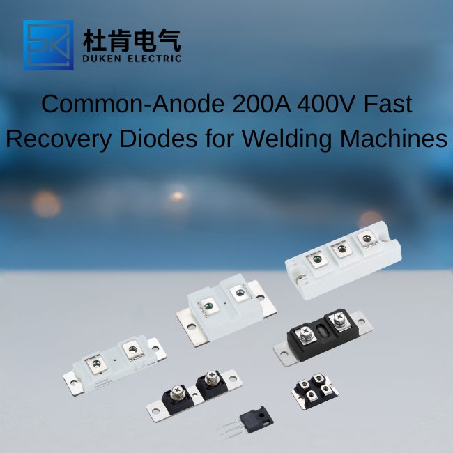
Common-Anode 200A 400V Fast Recovery Diodes for Welding Machines
Author: Selina
A 200A 400V fast recovery diode is often selected for industrial welding equipment because it combines high current capability, controlled reverse recovery, and manageable conduction loss. In common-anode rectifier assemblies, the shared anode connection can simplify busbar design and reduce connection complexity. For OEMs, the real value is not only the headline rating, but also reliable performance during repeated current pulses, rapid load changes, and elevated internal temperatures.
Why Welding Rectifiers Need Fast Recovery Performance
Welding machines operate under highly dynamic conditions. Output current can change within milliseconds as the arc starts, stabilizes, and stops. During these transitions, the rectifier diodes must commutate current quickly while controlling reverse recovery current. A slow diode can increase switching stress on transformers, IGBTs, and MOSFETs, especially in inverter-based welding platforms.
Reverse recovery is the period in which a diode continues to conduct briefly after the applied voltage reverses. The stored charge removed during this interval produces additional current and heat. In a high-current welding system, excessive recovery charge can cause voltage overshoot, EMI, and repeated thermal stress. A fast recovery device limits this effect and improves the stability of the power stage.
Common-Anode Configuration
A common-anode dual diode contains two diode elements with their anodes connected internally. This layout is useful in center-tapped or custom rectifier circuits where the shared anode must connect to a common bus. It can reduce external joints, shorten current paths, and simplify assembly.
However, common-anode and common-cathode devices are not interchangeable. Purchasing teams should verify the circuit diagram, terminal labeling, stud polarity, and mechanical outline before approving a substitute.
How Low Conduction Loss Improves Welding Efficiency
At 200A, a small difference in forward voltage creates a significant change in heat generation. Conduction loss can be estimated by multiplying forward voltage by average current. If one diode drops 1.25V and another drops 1.10V at the same current, the difference is 30W at 200A.
Lower loss provides several system-level benefits:
Reduced heatsink temperature
Lower fan speed or airflow requirement
Improved duty cycle at high output current
Less thermal stress on neighboring components
Higher long-term reliability
Key Parameters for Product Selection
| Parameter | Procurement Consideration |
|---|---|
| Average forward current | Confirm rating at the specified case temperature |
| Peak reverse voltage | Provide margin above transformer and switching spikes |
| Reverse recovery time | Match the inverter switching frequency |
| Forward voltage | Compare at realistic current and temperature |
| Surge current | Check pulse duration and repetition conditions |
| Thermal resistance | Use with the actual heatsink and mounting interface |
| Polarity | Verify common-anode terminal arrangement |
| Package | Confirm stud thread, dimensions, and torque |
Voltage Margin and Snubber Design
A 400V rating does not mean the diode should operate continuously near 400V reverse bias. Leakage inductance in transformers and wiring can create short voltage spikes that exceed the measured DC value. Engineers should review oscilloscope data under maximum load and line conditions, then choose suitable voltage margin and snubber protection.
Surge and Repetitive Pulse Capability
Welding current is pulsed by nature. The non-repetitive surge rating shown in a datasheet may describe only one half-sine event, not thousands of welding cycles. For production qualification, the diode should be tested with the actual current pulse width, repetition rate, cooling interval, and cabinet temperature.
Comparison with Standard Rectifiers and SiC Diodes
A standard rectifier diode may be acceptable in low-frequency transformer welders, but it generally has slower recovery and higher commutation stress. A fast recovery silicon diode is better suited to inverter welders using moderate switching frequencies and high current.
SiC diodes offer negligible reverse recovery and can reduce switching loss further. Their higher cost may be justified in very high-frequency or premium-efficiency designs. However, silicon fast recovery devices often provide a better balance of surge ruggedness, proven stud packaging, availability, and cost for mainstream industrial welding machines.
When comparing technologies, buyers should consider total system cost. A lower-priced diode that requires a larger heatsink, more airflow, or frequent replacement may not be economical over the equipment lifetime.
Qualification and Supplier Evaluation
Before approving a 200A 400V fast recovery diode, request complete electrical curves rather than only maximum ratings. Useful documents include forward-voltage graphs, reverse recovery conditions, thermal impedance curves, surge-current data, outline drawings, and mounting instructions.
Sample testing should include:
Full-load thermal measurement
Repeated arc-start cycles
Short-duration overload testing
High and low input-voltage conditions
Vibration testing for mobile welders
Post-test leakage and forward-voltage checks
For long-term purchasing, evaluate lot traceability, process-change notification, date-code control, packaging, and batch consistency. Distributors should also confirm whether the supplier can maintain the same die, package, and polarity configuration across future deliveries.
Conclusion
A common-anode welding rectifier must handle more than continuous current. It must survive repetitive pulses, control recovery losses, transfer heat efficiently, and maintain stable electrical characteristics over many operating cycles. Selecting a 200A 400V fast recovery diode with verified low forward voltage, suitable recovery speed, adequate surge margin, and correct polarity can improve welding duty cycle and reduce field failures. Careful qualification under real load conditions remains the most reliable way to confirm performance.
Frequently Asked Questions
What is the advantage of a common-anode dual diode?
It combines two diode elements around one internal anode connection, simplifying certain rectifier layouts and reducing external interconnections.
How does forward voltage affect a 200A welding rectifier?
Every 0.1V of forward drop represents about 20W of conduction loss at 200A, making voltage comparison important for thermal design.
Can a 400V diode be used without a snubber?
Only if measured transient voltage remains safely below the rating. Inductive spikes often require an RC snubber, clamp, or higher-voltage diode.
Is reverse recovery time the only switching parameter?
No. Reverse recovery charge, peak reverse current, softness, test current, and current slope should also be reviewed.
Should replacement diodes be tested in the actual welder?
Yes. Bench measurements alone do not reproduce real pulse current, cooling, transformer leakage, and switching conditions.
SEO Keywords: 200A 400V fast recovery diode, common anode diode, welding machine rectifier diode, low conduction loss diode, industrial welding diode, dual fast recovery diode, high current rectifier, stud type power diode, inverter welder diode, reverse recovery diode, high surge current diode, 200 amp diode, 400 volt diode, welding power semiconductor, common anode rectifier, low forward voltage diode, industrial diode supplier, welding equipment manufacturer, power electronics engineer, rectifier qualification, diode thermal design, inverter welding components, fast switching rectifier, high reliability diode, transformer welder rectifier, PWM welding diode, OEM diode manufacturer, power semiconductor distributor, diode sourcing guide, welding machine spare parts, dual diode module, high current semiconductor, rectifier busbar design, welding inverter supplier, component traceability, surge current testing, semiconductor qualification, thermal resistance diode, diode polarity selection, industrial rectifier sourcing
READ MORE:
A Procurement Guide to Qualifying a 200A 400V Fast Recovery Diode Supplier
How Dual 200A 400V Fast Recovery Diodes Improve Inverter Drive Reliability
Procurement Guide to Replacing 200A 400V Fast Recovery Diodes
Why Common-Anode 200A 400V Fast Recovery Diodes Matter in Welding Machines
How to Evaluate 200A 400V Fast Recovery Diodes for High-Surge Duty
How to Select a 3/4-16UNF Stud Type 200A 400V Fast Recovery Diode for Automotive Power Systems
Dual 200A 400V Fast Recovery Diodes for Reliable Inverter Drives
What Does Soft Recovery Mean in a 200A 400V Fast Recovery Diode?
200A 400V Fast Recovery Diode for High-Surge Automotive Power Systems