
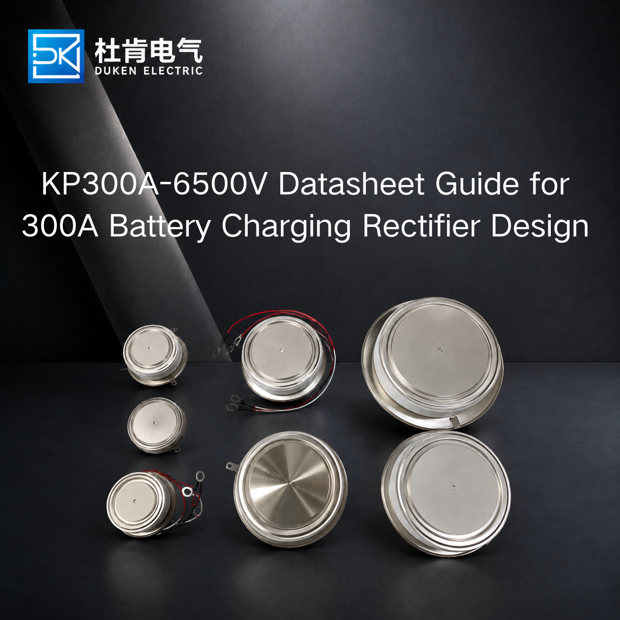
KP300A-6500V Datasheet Guide for 300A Battery Charging Rectifier Design
A 300A phase control thyristor cannot be approved for an industrial battery charging rectifier simply because its model number appears to match the required current and voltage. For engineers evaluating KP300A-6500V-class devices, the datasheet must be read as a set of interdependent electrical, thermal, triggering, and mechanical limits. A 6500V blocking rating may look impressive on an RFQ, but reliable operation depends on how that rating relates to the rectifier topology, AC input, transient environment, cooling system, and protection circuit. This guide explains how industrial OEMs and procurement teams should review a datasheet KP300A-6500V for battery charging rectifier projects before sample qualification or volume purchasing.
What KP300A-6500V Tells a Buyer—and What It Does Not
Model designations are useful for initial product identification, but they should never replace controlled technical documentation. A designation such as KP300A-6500V may indicate a phase-control thyristor family, an approximately 300A current class, and a high blocking-voltage option. The exact meaning, however, depends on the manufacturer's naming convention. Buyers should verify the manufacturer's datasheet instead of assuming that every parameter can be decoded from the part number.
This distinction becomes particularly important when sourcing replacement semiconductors from different manufacturers. Two products carrying apparently comparable current and voltage descriptions may differ in package dimensions, gate sensitivity, thermal resistance, surge capability, on-state voltage, recommended clamping force, or specified test conditions.
For a KP300A-6500V for battery charging rectifier, purchasing approval should therefore begin with a technical comparison rather than a commercial quotation. The engineering team should obtain the current datasheet, mechanical drawing, applicable quality information, and any customized specification associated with the offered device. If the component is intended to replace an existing SCR, the original part documentation should be placed alongside the proposed replacement for line-by-line comparison.
Why the 300A Rating Needs Context
One of the most common sourcing mistakes is treating a semiconductor's ampere rating like the rating printed on a cable or mechanical switch. Thyristor current ratings are associated with defined test conditions. The allowable current depends on factors including waveform, conduction angle, cooling reference conditions, junction-temperature limits, and package thermal characteristics.
A battery charger introduces another variable: the SCR current waveform depends on the rectifier topology and firing angle. For this reason, a charger delivering 300A DC does not necessarily impose a simple continuous 300A current on each individual SCR. Engineers should determine the current carried by each device during the relevant portion of the AC cycle and evaluate the appropriate average, RMS, and peak values.
This calculation is essential when comparing different thyristor models because devices advertised within the same nominal current class may be rated under different assumptions.
Reading the Important KP300A-6500V Datasheet Parameters
A datasheet contains many numbers, but procurement teams need to understand which ones can determine whether the component is suitable for the actual rectifier.
For a high-voltage 300A phase control thyristor, the first group concerns blocking capability. Repetitive peak off-state voltage and repetitive peak reverse voltage, where applicable to the device, define important voltage limits when the thyristor is not conducting.
The second group describes conduction. On-state voltage characteristics affect losses while the SCR carries current. Lower conduction loss can reduce the thermal burden, but a single typical voltage value should not be used as the entire thermal model. Engineers should use the appropriate curves or guaranteed limits provided by the manufacturer.
Surge current describes short-duration capability under specified conditions. It is particularly relevant when coordinating the SCR with semiconductor fuses and other protection devices. Triggering parameters determine whether the existing firing circuit can turn the device on reliably.
A practical review should include repetitive blocking voltage, average/RMS current, on-state voltage, surge current, I²t information, gate trigger current and voltage, holding/latching current, critical di/dt, critical dv/dt, thermal resistance, maximum junction temperature, package dimensions and clamping requirements. Values should be taken from the approved datasheet for the exact device revision. They should not be copied from a similarly named component.
Does a Battery Charging Rectifier Really Need 6500V?
Voltage selection deserves more engineering attention than simply choosing the highest available rating.
A datasheet KP300A-6500V for battery charging rectifier may be relevant to a high-voltage design or to an application requiring substantial blocking margin. However, whether 6500V is appropriate depends on the circuit.
The engineering team should begin with the actual AC input and transformer secondary conditions. Next, determine the maximum repetitive voltage appearing across each SCR in the chosen bridge topology. Supply tolerance, transformer behavior, switching events, inductive effects, and expected transient overvoltages must then be considered.
Protection components matter as well. Snubber networks, surge suppressors and other circuit elements can influence the voltage stress reaching the semiconductor. The goal is not to operate close to the blocking limit. Appropriate design margin is necessary. At the same time, specifying a substantially higher voltage class without a technical reason can reduce sourcing options or change other device characteristics.
This is particularly important for distributors and OEM purchasing departments. A request such as “300A, 6500V SCR” may attract multiple quotations that appear equivalent commercially while representing different technical solutions. A better RFQ states the required voltage rating together with the application and requests the supplier to confirm the proposed part against the operating conditions.
Gate Drive and Protection Cannot Be Ignored
The gate circuit is sometimes overlooked because it handles far less power than the main current path. Nevertheless, reliable triggering is essential to controlled rectifier operation.
The firing circuit must deliver sufficient gate current and voltage under the manufacturer's specified conditions. Temperature variation, pulse width, electrical noise and isolation architecture can all influence triggering reliability. Uneven or unreliable firing in a multi-device rectifier can produce poor output control and additional stress.
The engineer should also review dv/dt immunity. Rapid voltage changes can create unwanted triggering if the device and circuit protection are not adequately coordinated. Similarly, excessive di/dt immediately after turn-on can concentrate current within the semiconductor before conduction spreads sufficiently across the junction.
These considerations make the SCR, gate circuit, snubber, transformer and protection system a single engineering problem rather than independent purchased items.
Comparing SCRs With Rectifier Diodes, IGBTs and SiC Devices
The right semiconductor depends on what the charger is designed to do. A rectifier diode is the simplest option for an uncontrolled bridge. It turns on according to circuit polarity and requires no gate signal. This simplicity can be attractive, but it does not provide the adjustable phase-angle control available from an SCR.
The 300A phase control thyristor is useful when a line-frequency rectifier requires controlled output. It can regulate average DC output through firing-angle adjustment while handling substantial current with a relatively straightforward gate-control architecture.
IGBT-based chargers operate differently. An IGBT can be turned both on and off by its gate drive, enabling PWM converter topologies. This capability can support higher switching frequencies and more advanced power-conversion architectures, but it also introduces different gate-drive, magnetic, EMI and protection requirements.
Silicon MOSFETs are common in switching power supplies where voltage and current requirements match their strengths. SiC MOSFETs and SiC modules extend fast switching into higher-voltage power conversion and can improve efficiency and power density in appropriately designed systems.
For procurement teams, the important point is that these devices should not be compared solely by current and voltage ratings. Rectifier diodes offer simple rugged rectification but no controlled firing; SCRs provide high-current phase-controlled rectification but cannot normally be gate-turned-off; IGBTs provide controllable high-power PWM switching but require a different converter architecture; silicon MOSFETs support efficient high-frequency switching in suitable ranges; and SiC modules offer high-frequency, high-voltage efficiency and power density but are not direct SCR replacements.
For an existing industrial SCR charger, changing semiconductor technology usually means redesigning more than the power device itself.
How to Qualify KP300A-6500V Before Volume Procurement
A technical datasheet review should be followed by physical sample qualification.
First, verify mechanical compatibility. For a disc-type device, compare diameter, thickness, electrode surfaces, polarity identification, gate connection and specified clamping requirements. A device that fits poorly can create uneven pressure or inadequate thermal contact.
Second, confirm the gate-drive interface at realistic operating temperatures. Reliable firing should be checked throughout the expected input and load range.
Third, perform loaded thermal testing. The charger should operate long enough for temperatures to approach steady conditions. The engineering team can then use measured heatsink or case temperatures together with the supplier's thermal data to assess junction-temperature margin.
Fourth, evaluate relevant abnormal conditions. The exact tests depend on the equipment design, but may include controlled overload behavior, input variation, startup conditions and protection response.
For a customized KP300A-6500V for battery charging rectifier, the approved specification should be frozen before mass production. Any agreed differences from a standard product should be documented clearly.
Procurement should also establish traceability expectations. Lot identification, inspection records, change control and consistent product marking are valuable when a semiconductor will be used in industrial equipment with a long service life.
When qualifying an alternative supplier, avoid approving a device simply because one engineering sample passes. Production consistency is the real B2B requirement. Where appropriate, multiple samples or production lots should be evaluated against the critical characteristics identified by engineering.
Building a Better RFQ for 300A Thyristor Sourcing
An effective RFQ reduces unnecessary exchanges between engineering, procurement and the semiconductor supplier.
Instead of requesting only a “300A 6500V SCR,” provide the rectifier topology, AC input conditions, expected device current, ambient temperature, cooling method, mechanical package requirements and gate-drive information. If the project involves 300A phase control thyristor customization, identify the characteristics that genuinely require customization.
For replacement projects, include the original model number and datasheet. State whether exact mechanical interchangeability is mandatory or whether modifications are acceptable.
Buyers should also distinguish between absolute requirements and preferred characteristics. For example, a particular disc diameter may be mandatory because of an existing clamp, while a lower on-state voltage may be desirable but not essential.
This distinction allows suppliers to propose technically viable alternatives without creating ambiguity about the parameters that determine qualification.
Commercial evaluation can then consider lead time, minimum order quantity, documentation, traceability and supply continuity after engineering suitability has been established.
Conclusion
A KP300A-6500V-class thyristor should be purchased as an engineered component, not as a combination of two headline numbers. For battery charging rectifiers, the datasheet must be interpreted in the context of actual current waveforms, repetitive voltage stress, transients, conduction losses, gate triggering, thermal conditions and mechanical installation.
A properly selected 300A phase control thyristor can provide rugged and controllable rectification for industrial charging equipment, but reliable sourcing requires technical verification before price comparison. By reviewing the complete datasheet, coordinating protection and gate-drive requirements, validating samples under realistic loads, and documenting customized specifications, OEMs and distributors can reduce qualification risk and establish a more dependable long-term supply strategy.
FAQ
1. Does KP300A-6500V automatically mean 300A continuous current and 6500V operation?
No. The model designation should not be treated as a complete operating specification. Current and voltage ratings must be interpreted according to the manufacturer's datasheet definitions, test conditions and applicable thermal limits.
2. Which KP300A-6500V parameters are most important for a battery charging rectifier?
Engineers should review blocking voltage, current ratings, on-state characteristics, surge capability, thermal resistance, maximum junction temperature, gate parameters, di/dt, dv/dt and mechanical mounting requirements.
3. Why should surge current and I²t be reviewed together with fuse selection?
Semiconductor protection depends on how quickly fault energy is limited. The thyristor's short-duration capability and applicable I²t information should be coordinated with the selected semiconductor fuse and the actual fault characteristics of the circuit.
4. Can a 6500V thyristor replace a lower-voltage SCR directly?
Not automatically. In addition to voltage capability, compare current characteristics, losses, gate requirements, thermal performance, package dimensions and mounting conditions. Higher blocking voltage alone does not establish interchangeability.
5. What documents should a B2B buyer request before approving a customized thyristor?
Request the controlled datasheet, mechanical drawing, customized specification where applicable, relevant inspection or test information, product identification details and agreed traceability requirements. Samples should then be validated in the intended application before volume procurement.
Related SEO Terms: 300A phase control thyristor; KP300A-6500V; KP300A thyristor; KP300A SCR; 6500V thyristor; 6500V SCR; battery charging rectifier; battery charger thyristor; SCR datasheet; thyristor datasheet; high voltage thyristor; high current SCR; industrial rectifier SCR; phase controlled rectifier; controlled bridge rectifier; SCR voltage rating; thyristor blocking voltage; thyristor current rating; SCR surge current; thyristor I2t; gate trigger current; gate trigger voltage; thyristor di/dt; thyristor dv/dt; SCR thermal resistance; thyristor junction temperature; disc thyristor; disc package SCR; high voltage rectifier; industrial battery charger; power semiconductor; SCR rectifier; thyristor selection; SCR replacement; custom thyristor; thyristor customization; semiconductor fuse coordination; OEM thyristor sourcing; industrial SCR supplier; rectifier semiconductor selection