
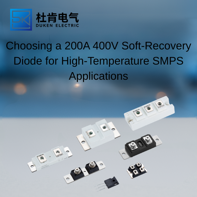
Choosing a 200A 400V Soft-Recovery Diode for High-Temperature SMPS Applications
A 200A 400V fast recovery diode used in a high-power switch-mode power supply must remain stable under rapid commutation, elevated junction temperature, and repetitive thermal cycling. In industrial SMPS platforms for telecom power, welding, battery charging, automation, and energy systems, the diode’s recovery behavior directly affects efficiency, electromagnetic interference, and the stress applied to IGBTs or MOSFETs. For procurement teams and design engineers, a high-temperature soft-recovery device should be evaluated as part of the full switching loop rather than as an isolated component.
Why Soft Recovery Matters in an SMPS
When a diode changes from forward conduction to reverse blocking, stored charge must be removed from the junction. This produces a reverse recovery current. If the current falls abruptly, the combination of high di/dt and circuit inductance can create voltage overshoot, ringing, and electromagnetic noise.
A soft-recovery diode transitions more gradually after reaching peak reverse current. This reduces the severity of the current tail and can lower overshoot across the switching device. The result is often easier EMI control, reduced snubber dissipation, and less electrical stress on the converter.
A for SMPS high temperature 150°C soft recovery type 200A 400V fast recovery diode is particularly valuable in enclosed equipment, compact power stacks, or industrial installations where ambient temperature and cooling conditions are difficult. The device must maintain predictable recovery characteristics as the junction approaches its upper operating range.
Electrical Parameters to Review at 150°C
Reverse Recovery Charge
Reverse recovery charge, Qrr, represents the total charge removed during commutation. It is a major contributor to switching loss. Lower Qrr generally reduces the energy that the transistor must absorb during turn-on, but recovery softness and peak current remain important.
Qrr should be compared at the same forward current, reverse voltage, di/dt, and junction temperature. A room-temperature value measured at a low current is not sufficient for a 200A industrial design.
Reverse Recovery Time
Reverse recovery time, trr, indicates the duration of the recovery event. Although it is useful, trr alone does not describe the shape or energy of the waveform. Two diodes may have similar trr values but very different peak recovery current and softness.
For an SMPS operating at tens of kilohertz, even modest differences in recovery energy can create substantial total loss over millions of switching cycles.
Forward Voltage Drop
Forward voltage, VF, determines conduction loss. At 200A, a 1.2V drop represents about 240W during conduction. The actual average loss depends on duty cycle and waveform, but small changes in VF can still affect heatsink size and internal temperature.
Buyers should review VF curves at elevated temperature. Some devices show lower forward voltage as temperature rises, while leakage and switching loss increase. The best choice depends on the combined conduction and switching-loss profile.
Reverse Leakage Current
Reverse leakage rises strongly with junction temperature. At 150°C, excessive leakage can increase standby loss, reduce voltage margin, and indicate weak process control. The datasheet should provide a maximum high-temperature leakage value rather than only a typical room-temperature figure.
Thermal Design for Reliable 150°C Operation
A maximum junction rating of 150°C does not mean the diode should operate continuously at that temperature. Reliable industrial designs usually maintain meaningful margin to account for airflow degradation, dust, production variation, overload, and sensor error.
The complete thermal path includes junction-to-case resistance, interface resistance, heatsink performance, and ambient temperature. The design should also include switching loss, not only forward conduction loss.
Estimate Total Power Loss
Total diode loss can be divided into conduction loss, reverse recovery loss, and leakage loss. In a high-frequency converter, recovery loss may become a significant portion of the total. Engineers can estimate switching energy from measured voltage and current waveforms and multiply by switching frequency.
Testing should be performed at the expected hot-state operating point. A diode that appears efficient at 25°C may generate more recovery charge and leakage at high temperature.
Validate the Cooling Assembly
Thermal validation should use the intended heatsink, interface material, airflow, and mounting pressure. Thermocouples or calibrated sensors should be positioned close to the package, and thermal imaging can help identify uneven contact.
For a 200A 400V fast recovery diode, the heatsink must be evaluated during normal load, startup, overload, and fan-degraded conditions. If liquid cooling is used, coolant temperature and flow tolerance should be included.
Application Fit and Topology Considerations
Soft-recovery diodes are used in boost stages, full-bridge and half-bridge converters, phase-shifted full bridges, welding power supplies, battery chargers, and high-power flyback-derived circuits. Their role may be freewheeling, secondary rectification, clamping, or commutation.
In a flyback converter, the diode must handle pulsed secondary current and transformer leakage spikes. In a bridge converter, it may commutate against a MOSFET or IGBT at high di/dt. The required recovery behavior depends on topology, switching frequency, transformer design, and parasitic inductance.
At higher power, a module package can simplify current handling and thermal management. A ceramic-insulated package may reduce assembly complexity, while a non-isolated module can offer a shorter thermal path. The correct package depends on whether the heatsink or cold plate is electrically grounded.
Comparison with Alternative Diode Technologies
Compared with a standard rectifier diode, a soft-recovery fast diode provides much lower switching loss and reduced commutation stress. Standard rectifiers remain suitable for low-frequency input bridges but are usually inappropriate for fast secondary or freewheeling paths.
Compared with a Schottky diode, a silicon fast-recovery diode usually handles higher voltage more economically. Schottky devices can offer lower forward drop, but leakage rises rapidly with voltage and temperature.
Compared with a SiC diode, a silicon soft-recovery diode has measurable Qrr and higher switching loss. SiC diodes offer near-zero reverse recovery and excellent high-temperature behavior, making them attractive for very high-frequency or high-efficiency designs. Their higher cost may be difficult to justify in price-sensitive industrial equipment.
Compared with the body diode of a MOSFET, a dedicated fast-recovery diode often provides better controlled recovery and lower stress. In some topologies, an external diode is added to improve switching behavior even when the transistor already includes an intrinsic diode.
Compared with an IGBT co-pack diode, a separate module gives the designer more freedom to optimize current rating, thermal layout, and replacement strategy. The trade-off is additional assembly complexity.
Model Selection and Supplier Qualification
When selecting a device, buyers should compare guaranteed values for:
Average and RMS forward current
Repetitive reverse voltage
Forward voltage at hot conditions
Qrr, trr, and peak recovery current
Recovery softness
Maximum junction temperature
High-temperature reverse leakage
Junction-to-case thermal resistance
Surge current and I²t
Package isolation and mounting requirements
The supplier should provide the recovery test circuit and conditions. Without them, datasheet comparisons can be misleading. Production traceability, statistical process control, change notification, and failure-analysis capability are also important for long-term OEM programs.
Qualification testing should include hot-state double-pulse or commutation testing, repeated thermal cycling, high-temperature reverse bias, surge testing, and extended operation at the intended switching frequency. Engineers should monitor the diode waveform together with the voltage and current of the associated MOSFET or IGBT.
For incoming inspection, practical checks include forward voltage, reverse leakage, package dimensions, terminal finish, markings, date codes, and lot records. Critical projects may require periodic recovery-waveform sampling.
Conclusion
A high-temperature soft-recovery diode should be selected according to its full hot-state switching behavior, not simply its 200A and 400V ratings. Qrr, recovery softness, VF, leakage, thermal resistance, and topology all influence converter efficiency and reliability. A well-qualified 200A 400V fast recovery diode can reduce EMI, protect switching transistors, and maintain stable performance in demanding industrial SMPS applications.
Frequently Asked Questions
1. Is 150°C a recommended continuous operating temperature?
No. It is usually a maximum junction rating. Reliable designs maintain margin below it for aging, cooling variation, and overload.
2. Why is soft recovery useful in an SMPS?
It reduces abrupt current transitions, helping lower voltage overshoot, ringing, EMI, and stress on MOSFETs or IGBTs.
3. Is Qrr more important than trr?
Both matter, but Qrr is often more useful for estimating switching energy. Peak current and waveform softness should also be reviewed.
4. When should SiC replace a silicon fast diode?
SiC is attractive when high switching frequency, efficiency, and thermal performance justify its higher cost.
5. What is the best qualification test?
A hot-state commutation test under the intended current, voltage, di/dt, and switching frequency provides the most relevant evidence.
Meta Title: 200A 400V Soft-Recovery Diode for Hot SMPS
Meta Description: Select a 200A 400V soft-recovery diode for 150°C SMPS operation by Qrr, trr, leakage, thermal design, topology, and supplier quality.
Focus Keyword: 200A 400V fast recovery diode
Author: Selina
READ MORE:
200A 400V Fast Recovery Diode Reliability and Procurement Guide for OEM Buyers
How to Choose a Ceramic-Insulated 200A 400V Fast Recovery Diode for Flyback Converters
How to Select a Heavy-Duty Non-Isolated 200A 400V Fast Recovery Diode Module
How to Test the Performance of a 200A 400V Fast Recovery Diode
How to Source 200A 400V Fast Recovery Diodes for OEM Bulk Production
Common-Anode Dual 200A 400V Fast Recovery Diodes for Industrial Power Conversion
Selecting a Dual 200A 400V Fast Recovery Diode with Low Reverse Leakage Current
Automotive Applications of Ultra-Fast 200A 400V Fast Recovery Diodes in Welding Systems
Top 10 Brands Producing 200A 400V Fast Recovery Diodes in 2026